Proposta laboratorio Automazione 2 Link
elenco analitico schede tecniche delle apparecchiature Link
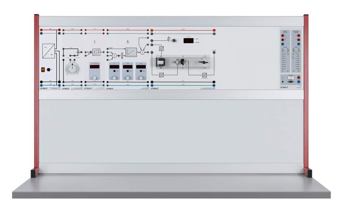
E6.3.1.1 Controllo di temperatura
Il controllo di temperatura funziona con un controller a due punti e con controller PID ed anche via software. Ha un display a 7 segmenti per la visualizzazione della temperatura. Una lampada alogena simula la fonte di calore e garantisce anche la visibilità del processo di riscaldamento. La temperatura viene misurata con un termistore NTC. Un ventilatore e una valvola a farfalla sono disponibili nella camera di riscaldamento per verificare il comportamento al disturbo. Due amplificatori di potenza integrati (per riscaldamento e raffreddamento) facilitano l'attivazione diretta con il controller. Il sistema a temperatura controllata può essere utilizzato anche con controllo fuzzy. Le prove sono eseguito con un manuale digitale i file dati sono forniti per il software di misura CASSY lab 2 e WinFACT.
|
|
Temi trattati nel manuale allegato:
Characteristic curve for the temperature controlling system Recording the jump response Optimal amount, replacement controlled system Technical controller Controller in the limit range Empirical tuning of controllers Control unit design with known time constants for the controlled system Controller design zero-pole compensation, KP determination in batch run Control unit design through numerical optimization |
Rule of thumb method Setpoint and disturbance control with electronic controllers Temperature regulation with a software controller Temperature controlling with block-oriented PC simulation Temperature control with two-point controller, influence of hysteresis Two-point controller with delayed feedback Two-point controller with delayed weakening feedback Temperature regulation with three-point controller Control circuit modelling |
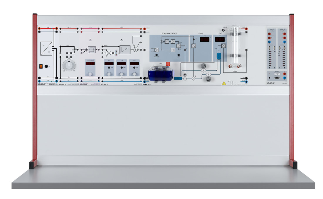
E6.3.1.2 Controllo di flusso e livello
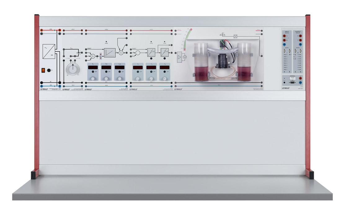
Il sistema è costituito principalmente da una pompa e da un serbatoio di raccolta e uno di misurazione. L'afflusso e il deflusso del liquido può essere regolato mediante due valvole. Il sistema è provvisto di misuratore di portata e un tubo ad immersione che registra il livello e consente anche la misura della pressione. Le prove sono eseguito con un manuale digitale i file dati sono forniti per il software di misura CASSY lab 2 e WinFACT.
|
|
Temi trattati nel manuale allegato:
Control design through pole-zero compensation Determination of the controller gain Kp from a batch run Control unit design through numerical optimization Rule of thumb method Digital liquid controlled system Flow measurement Step jump response of the flow system Flow controlling Flow regulation at the stability limit Follow-up control for flow with ZN-optimised controller Disturbance behaviour of flow controlling |
Flow controlling with block-oriented PC simulation Characteristics of the fill level system Fill level measurement Integral and PT1 behaviour of the fill level system Static identification of the fill level system Software-assisted controller selection Setpoint controlling of the fill level Disturbance control of the fill level Fill level controlling with a two-point controller Fill level controlling with PC simulation |
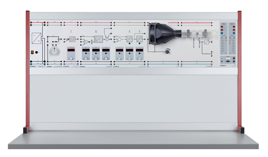
E6.3.1.3 Controllo del flusso d'aria
Il sistema è composto da un sensore per misurare il flusso e un generatore eolico controllabile. Il generatore eolico può essere controllato da un regolatore PID. Il flusso d'aria viene misurato mediante un anemometro a turbina. Le prove sono eseguito con un manuale digitale i file dati sono forniti per il software di misura CASSY lab 2 e WinFACT.
|
|
Temi trattati nel manuale allegato:
Measuring airflow Step responses of the controlled system Evaluation of the step response with adjusting function Determination of the system parameters of a PT2 component Computer-based system identification Empirical optimisation for the airflow system |
Two-point controlling of the airflow system ZN optimisation for the airflow system ZN optimisation for the airflow system with PT2 prefilter CHR optimisation for the airflow system with PT2 prefilter Airflow controlling with software controller Controlling the airflow - simulation |
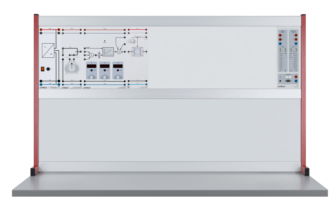
E6.3.1.4 Controllo di luminosità
Il sistema è fornito con sorgente luminosa a LED attivata direttamente dal regolatore PID. Lo schermo protettivo sul sensore luminoso diffonde uniformemente la luce, il sensore influenzato dalle frequenze alte dei semiconduttori ottici ha una risposta temporale simile a un sistema PT1. Le prove sono eseguito con un manuale digitale i file dati sono forniti per il software di misura CASSY lab 2 e WinFACT.
|
|
Temi trattati nel manuale allegato:
Characteristic curve for the temperature controlling system Recording the jump response Optimal amount, replacement controlled system Technical controller Controller in the limit range Empirical tuning of controllers Control unit design with known time constants for the controlled system Controller design zero-pole compensation, KP determination in batch run Control unit design through numerical optimization |
Rule of thumb method Setpoint and disturbance control with electronic controllers Temperature regulation with a software controller Temperature controlling with block-oriented PC simulation Temperature control with two-point controller, influence of hysteresis Two-point controller with delayed feedback Two-point controller with delayed weakening feedback Temperature regulation with three-point controller Control circuit modelling |
E6.3.1.5 Controllo di tensione e velocità
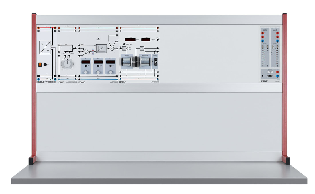
Il sistema da 10W è costituito da due motori a corrente continua e da un carico controllabile elettronicamente. I due motori sono collegati assieme tramite i loro alberi, uno è il motore vero e proprio mentre il secondo funge da generatore. Le prove sono eseguito con un manuale digitale i file dati sono forniti per il software di misura CASSY lab 2 e WinFACT.
|
|
Temi trattati nel manuale allegato:
Characteristic curve for the temperature controlling system Recording the jump response Optimal amount, replacement controlled system Technical controller Controller in the limit range Empirical tuning of controllers Control unit design with known time constants for the controlled system Controller design zero-pole compensation, KP determination in batch run Control unit design through numerical optimization |
Rule of thumb method Setpoint and disturbance control with electronic controllers Temperature regulation with a software controller Temperature controlling with block-oriented PC simulation Temperature control with two-point controller, influence of hysteresis Two-point controller with delayed feedback Two-point controller with delayed weakening feedback Temperature regulation with three-point controller Control circuit modelling |
|
Temi trattati nel manuale allegato:
Heeling control Step responses of the controlled system CHR optimisation for setpoint controlling Disturbance behaviour of the closed control circuit Model formation and simulation |
Simulated heeling control system at the limit for stability Simulated heeling control system with PT2 filter ZN optimisation of the heeling control system with PT2 Constant software controller Heeling control with three-point controller |

